
Open your WiFi SIP Phone for Repairs and Hacks
This one is not for the faint of heart. You will have to tug and pull your F1000G to pop it open. Why did I do it in the first place? My friend dropped a phone and the battery connector fell out of the PCB. The telephone was basically dead so I disassembled it to fix it. In the process I made an interesting discovery. Another Utstarcom F1000G WiFi phone hack is coming your way soon.
Step 1
Remove the battery cover and disconnect the battery. There are 4 screws holding the face and the back of the phone together. Take the screws out using a micro phillips screwdriver. The fourth screw may be hiding under a white round sticker near the battery connector. If your aim is to preserve UTStarcom warranty intact you may want to carefully remove the white sticker with a pointy object and save it so you can put it back in place later.
Step 2
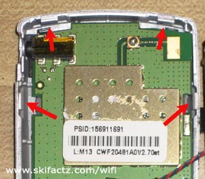
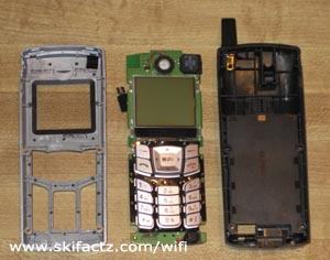
You will notice that you can pull apart the faceplate and the back of the phone at the bottom. There are four little snaps locking the back into the faceplate. Two snaps are on the sides and two are at the very top [Fig. 1]. They are really tight but we’ll pop them off with some force. Caution, the body of the phone may break. I’ve done this only once but I did not damage the plastic.
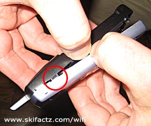
Hold the phone with both hands as illustrated in Figure 2 and pull. Pull hard but be ready to stop as soon as the snap pops out or else you may break the body. When the snap is out turn the phone around and pull out the matching snap on the other side.
Step 3
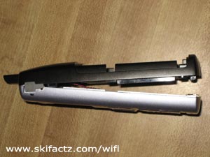
With two lower snaps out of place the faceplate and the back of the phone are held together by the remaining snaps at the top. The phone is now like a clamshell [Fig 3]. Pull the phone parts away from each other again but this time give them a little twist. It will feel like the phone body will break (and it may) but you may get lucky as me and get the darn thing to snap out. Only one snap will pop out at the time.
A Discovery
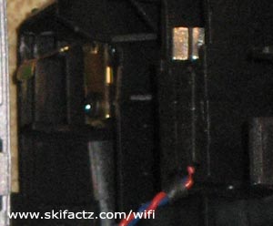
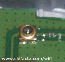
If you look closely at the lines leading to the antenna you will notice there is a little connector soldiered into the board [Fig. 7]. It’s very small. I think it may be a Hirose U.FL-R-SMT connector ready to accept an external WiFi antenna! As you may have noticed from the other projects listed on this page I’m a WiFi antenna kind of a guy. I’ll be hooking up some crazy microwave antenna to one of my wireless SIP phones soon. Small phone, big antenna, a recipe for enhanced WiFi telephony.