
Increase the Router Range with an External Antenna
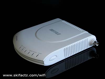
Buffalo WHR-G125 comes with a stock antenna permanently attached to the side. Some other routers like the popular Linksys WRT54G are equipped with detachable antennas that can be replaced with high gain counterparts. The “permanent” attachment in WHR-G125 is not so permanent after all. You can remove the antenna and install an external connector in as little as one hour [Fig 1].
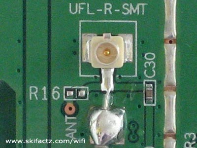
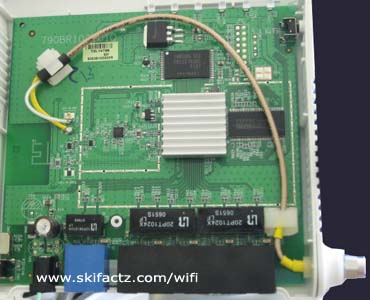
There is an alternative but more costly method to consider first. The board is equipped with a Hirose U.FL-R-SMT antenna connector [Fig. 2]. You could get a fitting pigtail and plug it directly into the board. These types of pigtails tend to be expensive.
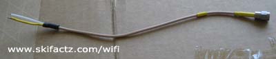
I opted for a solution that cost me $1 U.S. at an electronics swap meet. It’s a pigtail that has bare wires on one end and an SMA connector on the other end [Fig. 3]. Let’s learn how to do it.
First follow these instructions to open your WHR-G125.
Unsolder the stock antenna wires from the board. You should use a solder vacuum sucker and a soldering iron with a sharp tip. You don’t need a lot of heat.
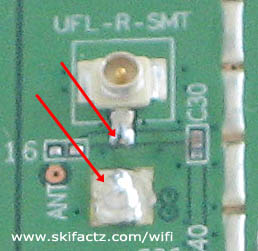
The onboard antenna connections are in close proximity [Fig 4] to each other and it’s easy for the molten solder to jump the contacts. If this happens don’t despair. You have not ruined the board. Just use the vacuum tool to remove excess solder.
Depending on the type of external connector you intend to use you could drill a hole in the router enclosure and mount the connector there. I decided to go for a non-invasive option that consists of taking out the original antenna and placing the connector in the hole where the antenna was attached.
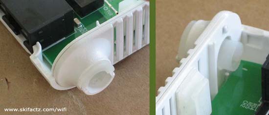
To remove the antenna squeeze the tabs as indicated [Fig. 5] and pull the antenna away from the router.

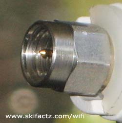
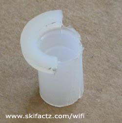
SMA size connector [Fig. 6] is a little smaller than the antenna hole. In order for it to fit snugly I used a bushing. It was necessary to cut half of the rim off [Fig. 7]. The reason I had to do this is clear once you look at the antenna hole.
When I inserted the bushing in the hole [Fig. 8] it was a little wobbly so I put a tiny dab of glue to hold it in place.
With the bushing in place you can thread the pigtail through. It is OK to force jam the connector in the hole so it stays still (that’s what we wanted). You can place a couple of self adhesive cable holders onto the PCB just avoid placing them on the board lines or the components. [Fig. 9]
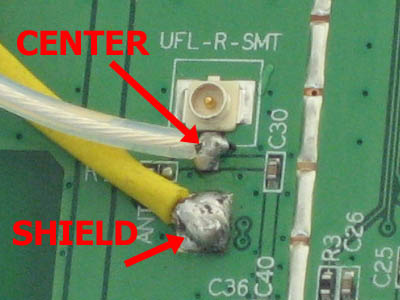
Solder the wires to the same board contacts where the stock antenna was connected. The center of the coaxial cable is connected closer to the miniature Hirose connector and the shield is connected to the square contact [Fig. 10]. Be careful that the solder does not jump the contacts.
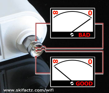
It is possible to test if the solder job is good with an Ohm meter. There should be no connectivity between the outer ring and the tip of your connector. If the Ohm meter reads “0” either your pigtail is bad or your new solder job is bad [Fig. 11].
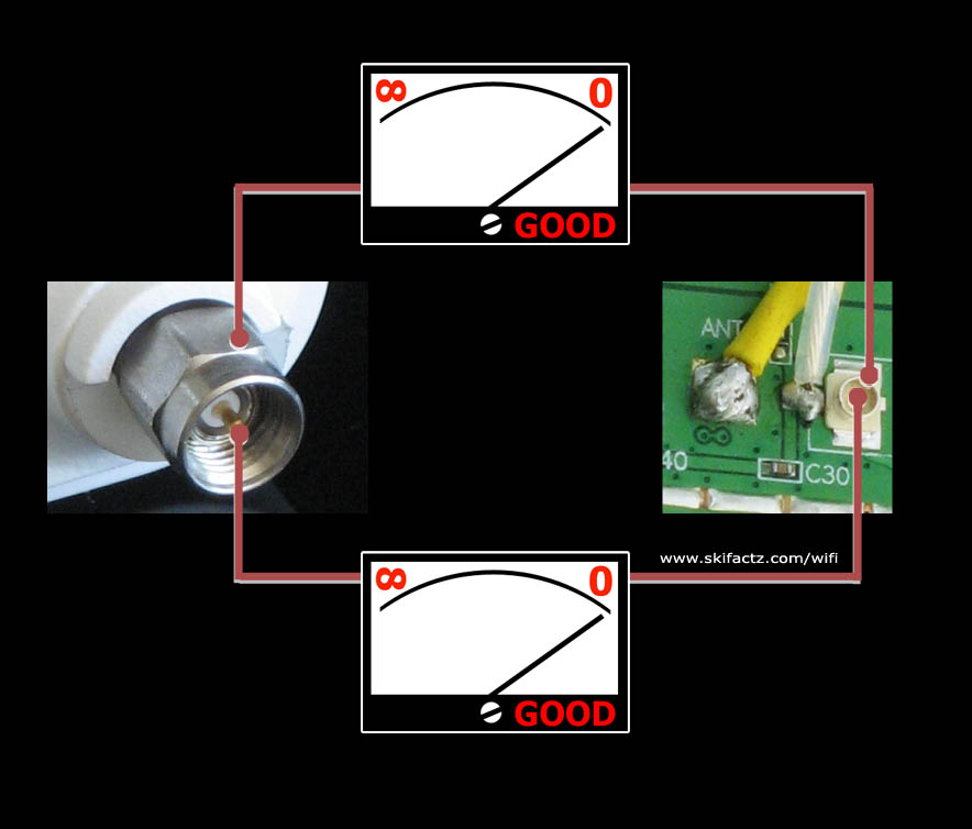
You can test your external connector further if you wish. There should be connectivity between the tip of your connector and the tip of on-board Hirose U.FL-R-SMT miniature connector. The outer ring of your external connector should also be connected to the outer ring of Hirose connector [Fig. 12].
That’s all it takes. Now you can snap the enclosure back in place and store the original antenna in a safe place in case you ever want to put it back on.