
Keep it Cool
Third party firmware for Linksys WRT54G series of wireless routers opened a world of possibilities. Firmware like Open WRT or DD-WRT allow access to features not available under Linksys stock firmware.
One of the unlocked features is Transmitter Power Adjustment. The chipset in WRT54G has a power output range of 0-250mW. The factory firmware locks the power to 28mW which limits the wireless range of the device.
Heat is an enemy of all electronics. It shortens the life of components. WRT54G does not come with a built in fan. Boosting the transmission power theoretically generates more heat. Various online forums have suggested that if you increase power from the default 28mW you could be slowly cooking the guts of your router.
Personally, I’m a bit skeptical this is true but I have decided to put a fan into one of my routers anyway because I use it outdoors in summer heat.
The reason I think WTR54G doesn’t burn hotter with increased power is simple. The device is drawing the same amount of current regardless of the transmitter power setting. On my WRT54GL I measured 240mA at 12V at all power settings from 0-250mW.
Tools Needed:
- soldering iron
- philips screwdriver
- wire cutters or scissors
- wire stripper or a sharp knife
- all surface marker (optional)
- heat gun (optional)
- drill, coping saw (if installing a switch)
Materials Needed:
- 12V fan, 1″ (2.5cm — you can use any larger fan as long as it fits in the housing)
- solder
- heat shrink tubing or electrical tape
- 3M double stick pad (the foamy kind with strong glue)
- electrical switch rated for 12V DC (optional)
- 18-22 AWG wire (just use wire that’s as thick as you can reasonably bend and fit into the housing)
- silicon based glue
Take the Router Apart
It’s a bit hard to pop open the router for the first time but it’s doable. Follow these instructions to open the router housing.
Tap Into the Power
Locate the power connector on the back of the unit and turn the PCB upside down. At the bottom side you will see two soldered pins [Fig. 1]. We’ll need to tap into them like in the photo.
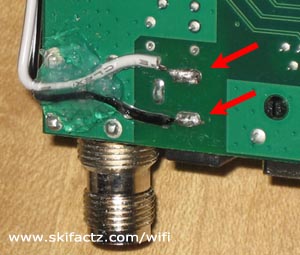
The wires that are attached to the 12V fan will likely be too short to reach the power on the bottom side of the PCB. You will need to extend them. Cut two pieces of wire. Give yourself enough length to reach the other side of the router. You can always cut off excess. Strip the ends and solder them into the power connector pins.
At this point you may want to loop the wire around the PCB and dab some silicon glue or sealant to attach the wire to the PCB [Fig. 1]. This last step is not necessary if you’re very careful while handling the board and the wire. The purpose the silicon dab is to prevent the wire from breaking off while you’re working on the fan. If you use silicon give yourself enough time so it is fully cured before you continue working.
A note on the wire gauge. Your fan is probably equiped with very thin wires so you may wonder why bother extending it with anything thicker than that. There is no real good reason for thicker wire. If there is a short circuit not prevented by the fuse in the power supply the thinnest wire in your router will burn. This is likely to be the fan itself. If your wire extensions are thinner than the fan’s coil there’s a chance they’ll burn first. If they are touching the PCB there could be further damage to the router. At least with thicker wire your’e increasing chances that the fan will melt instead of the router. That’s all. But what will really happen in case of a short circuit is anyone’s guess.
Install a Switch
Cut a hole in the top cover. Follow the instructions provided by the swicth manufacturer. Some toggle switches use a single round hole. Make sure that the switch is not too deep to short circuit the PCB or make installation physically impractical.
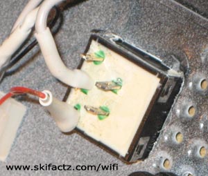
Square switches [Fig.2] need a square hole. Mark off the square area for the hole at desired location with an all surface marker. Drill a small hole in the center of the marked area. Pass the coping saw through the hole and tighten it. Cut the piece out with a saw. A small flat file comes in handy to trim down the edges once you’ve cut a hole. Be careful not to overcut. If you cut more than necessary your switch may be loose and will require gluing. The switch should snap into the hole (and stay in it) without use of force.
Solder Connections
Solder all the wires as indicated in the diagram [Fig. 3]. Thread suitable size shrink tubing on the wires prior to soldering. Once soldered use a heat gun to shrink the tubing. The idea is to insulate all exposed wire pieces. Any exposed wire can cause a short circuit. Alternately, you can use electrical tape.
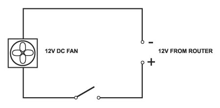
When connecting the fan pay attention to proper polarity. You want to have the fan suck the air out of the enclosure. Do it the easy way. Connect the power supply and temporarily attach the wires to the fan. If the air is not blowing out of the enclosure just reverse the polarity and soldier all connections.
Attach the Fan
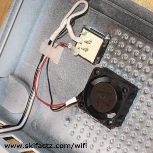
There is a number of ways you can attach the fan to the top cover but the one that will give you the most silent operation utilizes a piece of double stick tape. Simply affix a small piece of tape to the non moving body of the fan and attach the fan to the inside of the top cover [Fig. 4].
The tape must be cut small enough so there is no obstruction to the air flow. Use caution when handling the fan. I broke my first fan by applying too much thumb pressure on it.
You can also see in the picture that I used a self adhesive wire clip. This is not essential but it keeps everything clean.
Reassemble all the Pieces
Congratulations. All you have to do now is reassemble the pieces.
Snapping the WRT54G housing will require several medium intensity taps. Use the palm of your hand and don’t be afraid to use more force if the pieces are refusing to snap in place. If you are right handed you may want to hold the router in your left hand clasping the back connectors. Use your right hand to tap the face cover piece in place. Tap left and right corners but avoid the middle of the router face cover.