All posts by Hakr

Solar Powered WiFi Router

Ditch the AC Adaptor and Use the Sun


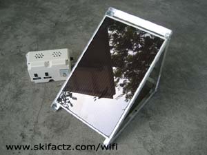
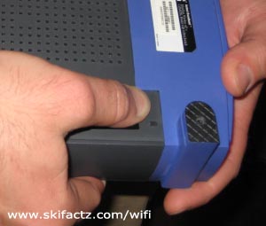
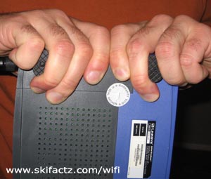
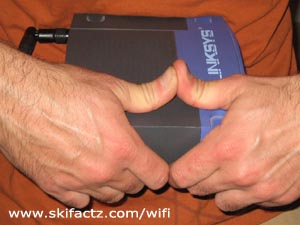
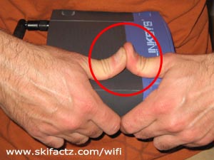
Solar panels are becoming so common that I got mine at a swap meet. It’s new and it cost me about $40 U.S.  My Linksys WRT54GL is off the grid now [Fig. 1]. If I can do it so can you.

Custom built solar charger for Linksys WRT54G
Fig. 1 Photovoltaic panel and 12V battery

The first thing to consider is that you will not be able to plug the router directly into the solar panel. I will name just a few obvious reasons:

  1. When the sun goes down it pulls the plug. No daylight, no power.
  2. The panel may have insufficient power output to run WRT54G series routers directly.

To overcome these issues I connected the router to a 12V battery and connected the battery to the solar panel. The panel provides a trickle charge. I don’t use this router every day so the battery has time to recharge.

WRT54GL draws about 240mA of current at 12V. Power is calculated by multiplying the current by voltage. Hence 0.24A X 12V = 2.88W. Note that 240mA equals 0.24A.

Unless you’re cheap like me you should purchase a panel from a reputable distributor. They will provide you with technical specifications. Luckily, photovoltaic panel output is often expressed in Watts so you can correlate that number to the 2.88W value of your router. Any panel more powerful than 2.88W should be capable to power up WRT54G. In reality that depends on the conditions outside of your control like cloud coverage for example.

Wiring diagram for a DIY solar WiFi router charger
Fig. 2 Solar battery charger schematics (click to enlarge)

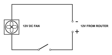
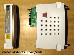
This wiring diagram should do the trick [Fig. 2]. I decided to install a switch for the solar panel to prevent overcharging the battery. Let’s say I win a 3-month tropical cruise raffle and go away with the router powered off. The battery could possibly overcharge. Overcharging a lead acid battery can cause battery damage and in rare cases can make the battery explode!

The panel switch disconnects the battery from the solar panel while you’re away. The second switch powers up the router.

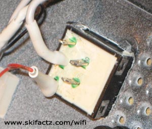
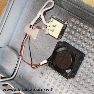
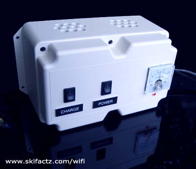
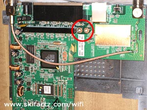
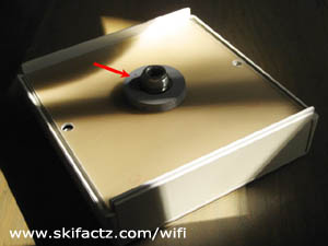
I added a LED power indicator and a Voltmeter [Fig. 3] but they are not indicated in the schematics for simplicity and cost.

Note that there is also a fuse [Fig. 2]. You should at least use a fuse rated for 500mA DC.

WiFi router outdoors battery. Custom assembly.
Fig. 3 The battery enclosure

Lead acid batteries are fairly safe but can explode and cause a fire. A fuse is a good safety device but there is always an inherent danger of fire and explosion associated with lead acid batteries and DC power. A short circuited battery can create very high current. High enough to melt your eyeballs out of the sockets.

On top of that lead acid batteries must always be charged in a well ventilated area. Even sealed batteries can have cracks that allow hydrogen gas to leak. Hydrogen plus electrical switch arcing is an explosive combination. Remember that newsreel film of Hindenburg coming down in flames? That aircraft was filled with hydrogen.

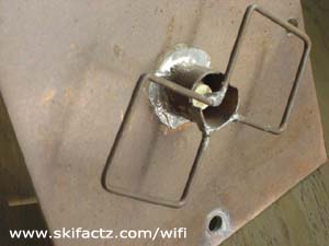
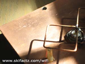
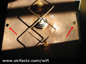
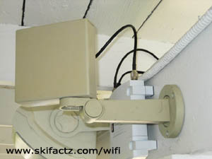
The Solar Panel Support

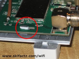
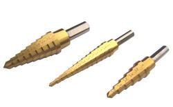
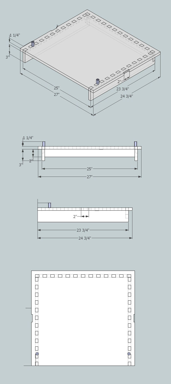
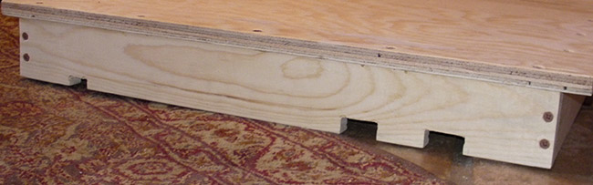
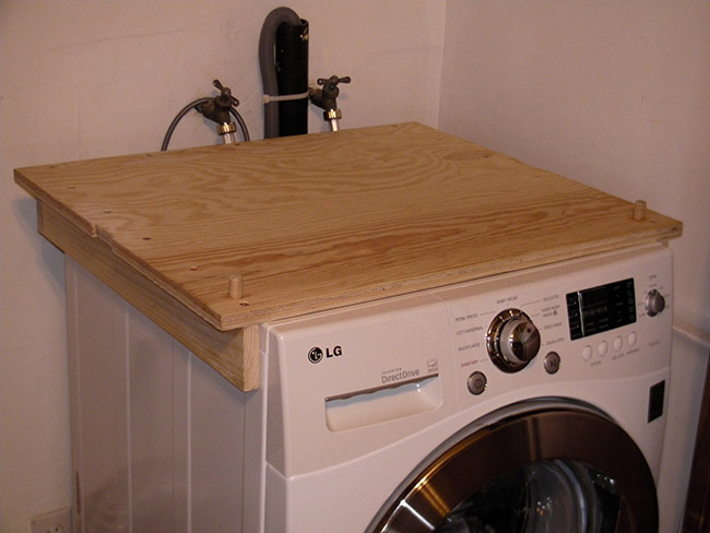
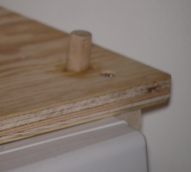
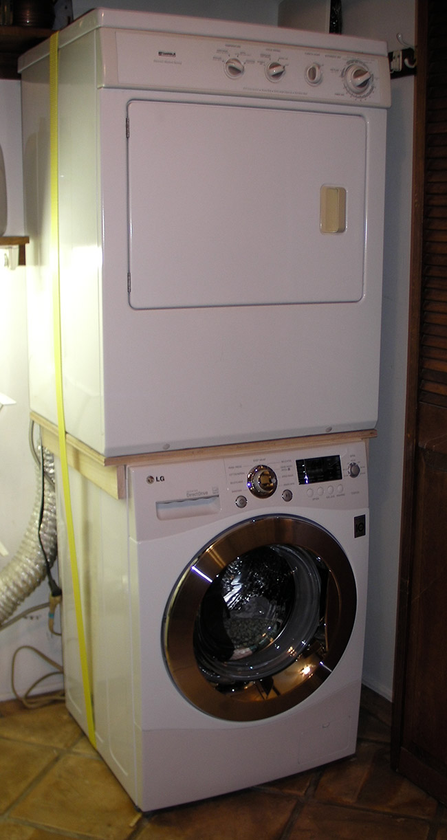
See the photos of aluminum frame I built for my panel [Fig 4]. Take them as a rough guide only. You may have different materials at hand or your panel may be constructed differently than mine. I drilled two holes in the legs of the frame so I can drive screws into a flat roof. Any time you screw something into the roof you’ll need silicon sealant to prevent water leaks.

Outdoors wireless internet charging solar panel DIY project.
Fig. 4 The aluminum frame support for the solar panel

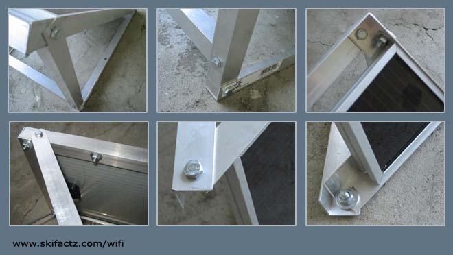
Generally, the panel should be set at 45 degrees and oriented towards the sun. Avoid areas where there may be shadows that move as the day progresses. If your area is clear of shadows in the summer, the winter may be a whole another story.

If you live in an area that receives lots of rain consider sealing all electrical contact boxes on the panel with silicon to block moisture from short circuiting the panel. Excessive snowfall can bury your panel for a while and cut off the battery from daily power supply.

Use a good thick copper wire to connect the panel to the battery. As I have already mentioned, during a short circuit batteries can create quick and powerful current spikes that will melt wires. The fuse should take the beating but play it safe with something like AWG 17 (1.15mm) or thicker. There are also considerations for proper wire gauge that take into account wire length, voltage and current. There are plenty of places online that provide formulas and information on wire selection.
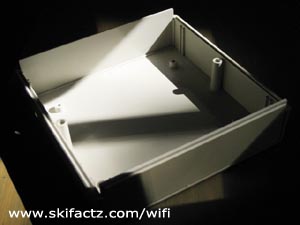
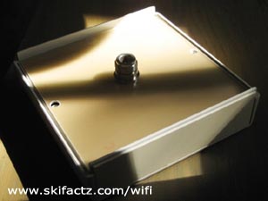
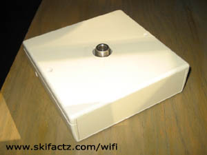
Battery Enclosure

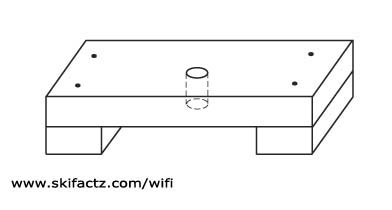
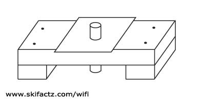
A couple of rules apply. Good ventilation is a must. You should have vent holes on top of the enclosure [Fig 3]. Hydrogen is lighter than air and will collect at the top of your box if there is a leak.

Metal enclosure is probably not the best idea. You could short circuit the battery if you touch the metal with the wire terminals. Short circuiting a 12V battery can cause premature death.

Mount your battery enclosure in a dry area.

This place has a great selection of equipment enclosures – http://www.polycase.com/.

Battery

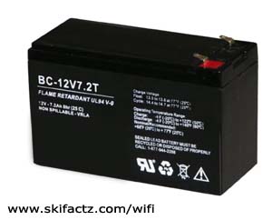
I got mine at the swap meet [Fig. 5]. Three used 12V 7Ah batteries for $5 U.S. Not a bad deal. If you are buying used look for cracks in the plastic. Explosive gas may leak through the cracks (although there may be cracks that you can’t even spot with a naked eye). A new battery is a better and safer choice.

12V battery for wireless internet router project
Fig. 5 12V 7Ah battery

You can get fancy and connect several batteries in parallel to increase capacity. This is done by connecting any number of batteries’ positive to positive leads and negative to negative leads. Just remember that this should be done with new batteries only. Otherwise you are reducing the used battery lifespan.

A single 7Ah battery should be enough to run your WRT54G for 29 hours.

You could use an old car battery. The only disadvantage is that some car batteries are not sealed. The acid can spill and they may require maintenance. Car batteries are also larger than the model shown in Fig. 5 and impractical for placing inside an enclosure. However, even a single car battery will make your router run for many, many days.

Odds and Ends

Make sure your switches are rated for at least 12V DC. Insulate all metal points of contact with either good quality electrical tape that will not unwind in heat or better yet with tube heat shrink.

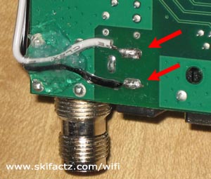
You can buy a premade DC cord with a plug that fits your router or you can get one from an old power supply. Make sure that the plug fits snuggly. Some cylindrical connectors seem to plug in well but are not thick enough and will drive you nuts when you jiggle the cord and reset the router.

Closing Thoughts

Is this project worth the effort? Probably not. You will spend more money than what you’d pay for electricity for the life of your router.

However, there may be some practical reasons why you may want to build a solar power supply. If you live in emergency prone areas where loss of power is common this solar powered router may come in handy.

If you’re a green freak you’ll love it (I hate to mention that manufacture of all the pieces hardware you’re about to use also contributes to CO2 emissions).

Most importantly, if you’re dealing with mid-life crisis like me this is a great little project to keep you busy for a week or two. The wife won’t mind either.

Take Linksys WRT54G Apart


Open the Screwless Assembly


Take Apart Your Linksys WRT54G Router
Fig. 1 Excersize the tab with your thumb
disassemble linksys router
Fig. 2 Grab onto the feet
pull apart WRT54G housing
Fig. 3 Get a firm grip and pull hard
opening WRT54G
Fig. 4 Thumb push method
WRT54G router taken apart
Fig. 5 Face plate removed
Location of PCB screws on WRT54G router
Fig. 6 Screws
Remove the board from Linsksys router
Fig. 7 PCB tab

Opening the router will void your warranty.

Since you have probably loaded third party firmware your warranty is gone anyway so you may as well pop the housing open.

There are no screws to remove. The pieces are snapped in place. The front face of the router will separate from the rest of the assembly.

Exercise the plastic with your thumb first [Fig 1].

At this point you are not loosening any snap locks. The purpose is to flex the plastic material so it will come off easier.

Clasp the feet of the router with your index fingers [Fig 2].

Lean the opposite side wall of the housing on your stomach. Hold onto the pieces tightly and pull [Fig 3].

The first time is the hardest. You will need a strong even pull. Don’t yank as you may end up throwing the router half the way across the room.

When the side you’re working on separates do the same on the opposite end. The other side will snap out easier.

There aren’t easily breakable plastic tabs inside. You could break a piece of plastic as this has happened to me on another router after 9-10 disassemblies but this came as a blessing. This particular WRT54G now opens really easily.

Every subsequent time you open your router will be easier than the previous. After several disassemblies you’ll be able to unsnap the pieces by pushing your thumbs apart [Fig 4].

Now that you have removed the face of the housing [Fig 5] take the main body of the router and remove the top. This is done by sliding the cover towards the back connectors.

The printed circuit board looks different in different models. In each case it is attached to the bottom of the housing by two screws [Fig. 6]. Remove the screws and slide the PCB off two small side locks [Fig 7].

A note about the WRT54G reset button

There are reports that the reset button retains some level of operation even when the router is powered off.

I highly doubt this but on this particular WRT54GL I accidentally reset the unit while installing a fan. This has probably happened while I had the opened router powered up. It is easy to bump the reset button if you are not careful.

So, before you even open the router take an extra step and back up your firmware adjustments. Take a note of the default IP address (probably 192.168.1.1) and the default user name and password (on DD-WRT “root” and “admin”). If you reset the router all settings will revert to default.

Build a WiFi Biquad Antenna

Martybugs.net 11dBi Biquad

Martin of martybugs.net has a great tutorial for building an 11dBi gain biquad WiFi antenna. You can follow his instructions here. Comparable gain antennas typically sell for around $100 U.S. The cost of materials used for Martin’s biquad should be around $15 U.S. Not a bad deal considering that you can build one in an afternoon.

I have built a number of biquads based on his design and done extensive practical testing. I’d like to share these insights with you. Study Martin’s tutorial and come back here for several tips that will make the construction and use easier.

Connecting the antenna to a computer

The antenna is going to boost your signal a lot. I have logged into a public hotspot from 23km (17m) using only the biquad in a moving vehicle! To be fair, I was in a rural area on a hill overlooking a small town. There was little in the way of interference from other microwave sources. The connection was not particularly good but 23km is unthinkable for stock antennas that come with consumer networking equipment.

When I first looked into the building one of these I didn’t quite understand how to connect the antenna to the computer. You can tap straight into your network card or motherboard. This is not for the faint of heart. You can cause permanent damage by soldering pieces onto your motherboard. A far easier solution in case of a laptop computer is to get a PCMCIA wireless card with an external antenna connector. I have a Buffalo WiFi card that works very well. Even without an external antenna it’s much more sensitive than my older Linksys cards.

To properly connect the wireless card to the biquad you will need a short adaptor cable called “pigtail.” Ebay is a great place for finding the right pigtail for your application. The cable is not particularly expensive. When purchasing one consider that that signal loss is proportional to the length of the pigtail. Choose as short of a pigtail as practical.

Sourcing the biquad antenna parts

The materials for the biquad are simple: copper wire, printed circuit board (PCB), copper pipe, coaxial cable and “N” type connector.

Depending on your locale you may have to mail order some of these parts. HAM radio stores and radio amateur swap meets are great places to get the stuff. Ebay is also a good place but expect to pay more because of shipping costs for individual items. I have ordered biquad kits on Ebay at a price that beats getting all components separately.

Along with microwave cable the “N” connector is probably the hardest piece to find. Special low loss microwave LMR 400 cable is recommended but the length of cable used in the antenna is so short that any 50 Ohm cable will work just fine.

Tools

Cutting copper pipe is a slow process unless you have a good metal saw. Another tool of great importance is the soldering iron.

You will need a lot of heat because of the heat dissipation in the large metal mass you are trying to soldier. My electric soldering iron was not working for this at all and I used a small butane torch from Radio Shack. I love this tool! It’s very versatile because it doubles as a soldering iron and there are no cables dangling.

Drill step bits
Fig. 1 Step bits by Fourman

Drilling the PCB is very easy but you will need a range of drill bits to build up the hole size for the copper pipe to fit through. One type of drill bit I find particularly useful for this type of work is called step bit [Fig. 1].

If you don’t have access to a good vise you can make a simple hands-free rig out of a short wood board. Drill a hole just barely tighter than the copper pipe in the middle of the board. Cut two short board pieces for feet and nail the board with a hole on top of them [Fig. 2].

This tool will allow you to jam the copper pipe tight into the wood and lay the PCB at a perfect 90 degrees angle [Fig. 3]. The metal pieces will get very hot during soldiering. Wear work gloves or avoid touching metal while hot.

Simple biquad assembly rig
Fig. 2 Simple biquad assembly bench
Copper pipe and square PCB on the rig
Fig. 3 Copper pipe and square PCB on the bench

Once you are finished building the biquad you may consider placing it in an enclosure for protection. See the enclosure building instructions.

Stack Washer and a Dryer

Incompatible appliances, no problem

If you have a laundry washer and a dryer from two different manufacturers and are wondering how to stack them up on top of one another, read on. I will demonstrate how I stacked my new LG WM1355HW washer with Kenmore 417.93142203 dryer. It cost less than $30 for materials and it took several hours to complete.

My matching Kenmore washer died beyond repair recently leaving me with a perfectly fine gas dryer. The two units were designed to safely stack together, but finding a new replacement washing machine that could stack with the existing dryer was impossible.

Allegedly washing machines are engineered to fail after eight years of use and my experience proves it. This is maddening, but the worst thing is that there is no standardization of any kind. Separately purchased units don’t stack. Dimensions vary widely. Manufacturers want you to replace the washer/dryer combos even if only one appliance fails.

Use this example at your own risk. If your machines topple over don’t say I didn’t warn you. I am not saying my stacking solution is safe, but it feels very sturdy. Make sure the washer is on the bottom.

Diagram for a washer dryer stacking platform

I build a coupling brace of 3/4” plywood and 3/4” thick boards. It snugly fits on top and hugs the sides and the back of the LG washer. Based on the connections on the back of your particular washer you may have to cut into the back board to allow access. I had to do this for the water connections and for the AC cable.

Although the diagram indicates something like finger joints between the boards and the top plywood, I used glue and wood screws to hold the pieces together.

The back of custom washer dryer brace
Cut indentations for water and AC connections

The drier is larger than the washer so the rectangular plywood top of the brace extends over the edges of the washer. On the left and the right of the brace I cut in two notches a little wider than 2” to keep the safety strap in place.

The bracing platform seen on top of the washer
The finished platform atop the washer

My dryer has removable feet that are screwed into the holes at the bottom of the unit. I glued two 1/2” round pegs into the top of the brace. The pegs perfectly match the placement of the holes on the front of the dryer.

Round peg inserts into a hole on the bottom of the dryer

Once I coupled the washer and dryer, I ran a 20′ long 2” ratchet strap around the two units and made it real tight. That’s all. The extra weight on the washing machine makes it vibrate less during the spin cycle. Two years later the dryer hasn’t fallen off!

Use custom brace to stack incompatible washer and dryer
Stacked washer and dryer

Housing for Biquad WiFi Antenna

Protect Your Outdoors Antenna

Two types of damage can affect a working antenna.

It can sustain physical impact and the copper wire may bend and break the soldiered point.

Copper oxidation on external WIFi antenna ager a month of use
Fig. 1 Oxidation after a month of use
Oxidation free copper on a housed antenna
Fig. 2 This biquad was housed

If exposed to rain the copper will oxidize which may eventually lead to decreased performance.

The antenna pictured in Fig. 1 was used outdoors for a month in almost no rain. The antenna on the right was used for the same amount of time in the same location but was enclosed. The difference is striking [Fig 2].

Both of these types of damage can be easily mitigated with proper antenna housing. You can use ready made electronics enclosures or even low end solutions like Tupperware containers. If you use Tupperware consider sealing it with silicon to prevent rain from getting in.

The enclosure can not be made of metal nor can have any metal foil decals on it. You must use a material that does not reflect microwaves.

Some materials may cause the signal strength to drop. You can conduct a simple test of microwave attenuation of your desired enclosure. Lock the antenna into a vise grip or a camera tripod and point it towards a distant access point. Connect the antenna to the computer and start Netstumbler. Run Netstumbler for several minutes. Then place the antenna housing in front of the biquad and observe the signal change in Netstumbler. If there is no change or change is rather small your box is acceptable as an antenna enclosure.

You can find equipment enclosures at electronics stores or mail order them. Polycase has a great selection of various enclosures and I used their products for other projects. The actual enclosure I used here is CM5-125 from Pactec. It’s a little tight for Martin’s biquad so I ended up belt sanding the edges of the PCB to make it fit in the box. The change of size does not seem to affect the antenna performance.

Drill small holes in the biquad PCB to match the hole configuration in the enclosure [Fig. 3]. Place the antenna face down into the enclosure [Fig 5]. Drill a center hole into the back of the enclosure so you can run the cable through it. I used a foamy ring from a 50 CD-R spindle as a gasket between the back of the antenna and the back of the enclosure [Fig. 6].

You will notice that the construction of the biquad pictured here differs slightly from Martin’s design but the same steps are valid for an antenna built exactly to his specifications.

biquad holes
Fig. 3 Drill holes to match the housing mount


equipment enclosure
Fig. 4 enclosure


antenna placed  in enclosure
Fig. 5 Place the antenna in the enclosure


gasket
Fig. 6 CD spindle foam ring


finished WiFi antenna
Fig. 7 Job done


WiFi antenna mount
Fig. 7 Professionally looking antenna


I strongly recommend using heat shrink tubing to protect the antenna’s soldiered connections from being ripped apart. The LMR 400 cable is very rigid. Since it can not flex much it can not absorb physical abuse and your point of soldier may fail. Shrink tubing is a special type of material (you can find it at Radio Shack) which will shrink when exposed to heat generated by a heat gun or a gas torch.

Heat shrink tubing on RF cable
Fig. 8 Heat shrink tubing on RF cable

Prior to soldering your “N” connector, dress the cable and the copper pipe with heat shrink tubing.

Mount and solder the connector and then shrink the tubing so it wraps tightly over the pipe and the cable. The other piece should cover the connector and the cable right next to it.

If you don’t have a heat gun you can use the propane torch but have to be carefull not to burn the cable and the shrink wrap. Test it on a small area first.

Turn Old Nextel Phone Into a Walkie-talkie

New life for obsolete Nextel phones

Sprint has killied the Nextel Motorola iDEN network in the United States. That’s too bad, but if you have a pair of Nextel phones you can turn them into very good two way radios that will function even without the cell phone network.

Many, if not all newer Motorola Nextel phones have the “off network mode” also known as MOTO Talk which turn the phones into walkie-talkies completely independent of the phone provider’s network. The radios don’t use encryption, although the privacy settings allow users to communicate with select private groups and to individual units.

A SIM card is mandatory, although network service is not. I suspect any SIM card will do the trick. Without one the phone just hangs up at a screen that ask to insert a SIM card.

Nextel phone off network mode menu
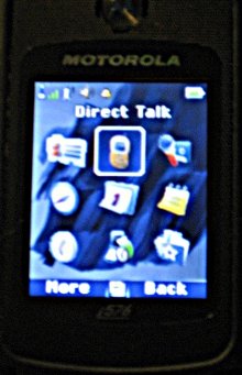
I tested a pair of Motorola i576 phones in an urban low-rise environment with hills and natural and man made obstacles occluding the line of sight. One unit was stationary and another was in a moving vehicle. I was able to transmit and receive completely clear voice up to one mile (1.5km) distance.

It is reasonable to expect that in a line of sight applications the range would be far greater. The range may also depend on the model of the phone.

To enable the off network mode simply go to the phone menu, turn the Direct Talk on and make sure the channel selection and privacy codes are matched on all the units you intend to use.

The U.S. Nextel network was shut down in 2013.

WiFi Antenna Pointer Tool

Scanmeter, WiFi Antenna Tuning Software for Linux

11/01/2015 update

You may also take a look at the new Python 2.x based antenna pointing tool called Scanmeternm.py.

Although there are many great WiFi related programs available for Linux there isn’t a good antenna setup software like the Netstumbler in Windows. Of course, Linux has the all powerful Kismet and the simple to use Wavemon but neither is very useful when it comes to measuring 802.11 RF signal level and plotting a histogram. I build and test high gain WiFi antennas as a hobby and need a simple measuring tool so I wrote Scanmeter which is a bash script that measures signal strength and displays the wireless strength in a histogram [Fig. 1].

WiFi antenna pointing software for Linux
Fig. 1 Scanmeter screen grab

High gain antennas are directional by design. When pointing a directional antenna it is important to measure the WiFi signal level as we move the antenna. Even when you know the general direction of the access point, small azimuth angle, elevation and polarization corrections can produce big differences in signal amplitude.

This is especially true for distant WiFi access points. Imagine shining a laser pointer at a building several blocks away. A small movement of hand will move the laser dot in large sweeps. WiFi antennas are not as focused as a laser beam but when going for distance every dB counts so it is important to aim right.

Scanmeter features a continuously updating histogram. While you are adjusting the position of your high gain WiFi antenna the signal is plotted on screen live so you can find the “sweet spot” without guessing.

Download and Installation

I have tested Scanmeter in several different configurations. If none matches your hardware that’s OK. Pick the closest one and modify the script if necessary. [LINK]

If you’re new to bash scripts do this:

  1. Download and unpack the script to your /home/yourname directory.
  2. Open a terminal window and type:
cd /home/yourname
chmod +x scanmeter

There are better places to save a bash script like /usr/local/bin for example. Look up a tutorial on saving and executing bash scripts for more information.

Scanmeter Usage

Scanmeter must be executed by the root user. This is done inside a terminal window:

  1. cd /home/yourname (navigate to the location of the script)
  2. sudo ./scanmeter [interface]
Scanmeter screen grab
Fig. 2 Scanmeter screen grab

The default interface is wlan0 except for the Dell Mini 9 factory WiFi card version which defaults to eth1. Your WiFi card could also default to eth1 or another device name. To find out the device name of your wireless card execute:

iwconfig

If you saved the script in /usr/local/sbin or added the custom location path to the PATH environment variable (slightly advanced), your Scanmeter can be executed by typing:

sudo scanmeter [interface]

or

sudo ./scanmeter [interface]

Scanmeter is very self explanatory. Make sure you use all caps when typing in the BSSID (MAC Address). Press CTRL+C to exit the histogram. Pressing enter in the main menu prompt will restart scanning with the last entered BSSID.

Debugging

Scanmeter parses the output of Linux command:

sudo iwlist interface scanning

The physical formatting of the iwlist command output depends on the wireless chipset, the driver and possibly the Linux distro. For this reason you may have to make minimal adjustments to the script to make it work.

Similar Software

Check out Pifimon which is a Perl script inspired by Scanmeter (and improved). If you improve scanmeter or make similar tools let me know please.

Improving WRT54G Repeater Performance

Repeater working slow? Overcome diversity.

One of the most practical uses for WRT54G wireless router in repeater mode is to redistribute distant gateway’s internet connection. The distant AP can in some cases be several kilometers away. You can attach a high gain directional antenna [LINK] to one of the WRT54G’s antenna ports to connect to a distant access point. In this setup the second Linksys stock antenna is used to provide local connectivity [Fig. 1].

Diagram of antenna unbalance on Linksys WRT54G repeater
Fig. 1 Using WRT54G as a repeater with asymmetrical antennas

The problem with the above setup is that you may suffer significant radio connection issues. Linksys WRT54G is designed to work with two symmetrical antennas (same kind, relative proximity) in so-called “diversity” mode. Attaching unequal antennas which cover different radio cells as in Fig. 1 is something diversity mode is generally not equipped to deal with.

What is this diversity mode? Linksys antennas are never both on at the same time. Diversity circuitry determines which antenna has better reception and switches it on in a fraction of a second while it turns off the other antenna. This complex behavior is necessary to overcome a radio phenomenon known as multipath distortion. I recommend a very good white paper by Cisco which explains multipath distortion and diversity in a very plain language.

Obviously diversity is designed with the idea that both antennas will be used in the same radio cell. Separating the antennas or using antennas of unequal gain inevitably causes one of the antennas to be favored by diversity circuitry which leaves the other antenna in the dark. The reality is not as black and white. It is not likely that you will experience a complete shutdown of one of the antennas but favoring one antenna will cause interrupted communication on the other antenna.

You can test how much service interruption you are getting. Connect to the repeater wirelessly and measure the internet upload and download speed. Repeat the measurement three times and take a note of the average speed. Then connect to one of the WRT54G LAN ports with an ethernet cable and take the same measurement. Compare the averages to see how much speed you’re losing because of diversity.

A simple way to overcome this problem is to disable the stock antenna and connect to the repeater through wired LAN connection only. Third party firmware like DD-WRT allow you to do just that.

A more effective solution albeit a more expensive one is to use two routers [Fig. 2]. The Linksys WRT-54G still works as a repeater station with the stock antenna disabled. A second router is connected to WRT54G through ethernet. I have chosen the Buffalo WHR-G125 for the second router because it generally outperforms WRT54G straight out of the box.

WiFi repeater setup with two routers for better performance
Fig. 2 WiFi repeater setup with two routers.

In this scenario the Linksys still works the same way repeating the distant access point. The second router WHR-G125 redistributes the signal locally. It also works as a switch so you can hard wire any local computers into the three available LAN ports (you can also hard wire into the WRT54G’s LAN ports).

You may ask why all the extra labor turning off the local antenna and connecting the second router. Why don’t we just use a router that doesn’t use diversity in the first place. Well, any router without diversity will have a single antenna by definition. It is perfectly fine to use such router with the stock or even a replacement high gain antenna. The problem is that if you are attempting to repeat an AP that is far away you will need a parabolic antenna [LINK] or a yagi. The radiation pattern of these antennas is concentrated in the front. In other words, they will connect to the distant AP just fine but may not leave a lot of useful signal behind them and your local radio cell will have unreliable coverage. This will cause your local WiFi connection to drop out frequently.

This example uses DD-WRT firmware which is available for both WRT54G and WHR-G125. Connect the two routers with a LAN cable and connect your computer to the second router with another LAN cable. You can also set up the router while connecting wirelessly but it is a bit more difficult. Unless you have just uploaded the firmware start clean by resetting to factory defaults. The factory reset is under “Administration” tab.

It is very helpful to change the GUI colors on one of the routers so you can always know which control panel you are logged into. You will find the color control settings under “Administration” tab as well [Fig. 3].

Change DD-WRT GUI color
Fig. 3 Change GUI color

Change the user name and password and take a note of them for later use [Fig. 4]. The default DD-WRT user name is “root” and password is “admin”

DD-WRT user name and password menu
Fig. 4 Change user name and password

You should pick a non-overlapping channel frequency for better performance [Fig. 5]. Channels 1, 6 and 11 do not overlap with each other in the United States. For example, if your repeater is broadcasting on channel 7 you can select either channel 1 or 11 on the second router. Everything will work even without proper channel assignments. This is just a precaution to avoid interference.

Also type in the SSID. This is the name you will see when connecting to the router wirelessly. It should be different from the SSID of the repeater.

DD-WRT SSID and channel setting menu
Fig. 5 Pick a SSID and change the channel number

The last and the most important step is to go to the “Setup” tab [Fig 6]. Under “Basic Setup” we’ll change the “Local IP Address” to place the second router in the repeater’s subnet. In this case the repeater IP is 10.0.0.1 so I changed the IP address on the second router to 10.0.0.120. The last place number (120) can be any number smaller than 255 and other than 0 or 1.

Select “Disable” under “DHCP Server” on the same page.

DD-WRT setup tab settings
Fig. 6 DD-WRT setup tab settings

At this point you are ready to connect to the internet as long as the repeater is working properly. The LAN ports on the WHR-G125 and the wireless connection are both available for use at this time. You can still access control panels for each router by entering their respective IP addresses into a browser. In this case 10.0.0.1 takes you to the repeater’s GUI and 10.0.0.120 takes you to the Buffalo router.

Linksys WRT54G in Repeater Mode

Unleash the Hidden Features Using DD-WRT

Overview

Linksys WRT54G router is capable of working in repeater mode with third party firmware like DD-WRT. A WiFi repeater is a device that will connect to another wireless access point and redistribute the signal. Repeaters are typically used to extend the coverage of a network in office buildings, hotels, convention halls, airports and other public spaces.

Repeaters can also be used on a smaller scale to share an internet connection with a neighbor. You can also use a repeater to set up a communal open hotspot and share the connection with a group of neighbors.

Installing DD-WRT

As of June 2007, DD-WRT beta v24 firmware is the only version that works in repeater mode. You can download it here. The download area is a bit confusing. Follow these steps to find the correct firmware:

  1. select “beta”
  2. select “GENERIC BROADCOM”
  3. select “dd-wrt.v24 beta”
  4. select the most current date

This last step will take you to a folder full of different versions of the firmware. You will need one or more files marked as “WRT54G.” To determine which one is appropriate for your version of WRT54G you need to consult the wiki. Some of the more recent versions of WRT54G have a RAM issue that can be overcome by installing the smaller “micro” version.

DD-WRT firmware is relatively easy to install and setup. The installation process varies slightly based on the version of the router you have. The older WRT54G models you can buy used on Ebay are better candidates for third party firmware installation.

Linksys has moved away from open source firmware in the new models of WRT54G. However, the current WRT54GL will still accept third party firmware. Not surprisingly, this model costs more than comparable units so stick to the used stuff when you can.

The official DD-WRT page is the best place to get installation instructions. There is some useful information in the wiki. The DD-WRT forum is better than the wiki although both presuppose you have basic networking skills. I had none prior to doing all this and still made it through. You can too.

A word about “bricked” routers

A “bricked” router is a malfunctioning router. It’s as usefull for networking as a brick. This is typically a result of a bad firmware flash. It is possible to recover a “bricked” device in most cases but there are varying degrees of difficulty. To avoid bricking always follow instructions carefully.

There are times when you may have to use TFTP to flash the router. If your operating system does not support TFTP you can download a free Linksys TFTP utility. It is very easy to use and has saved me several times.

A “bricked” router is a malfunctioning router. It’s as useful for networking as a brick. This is typically a result of a bad firmware flash. It is possible to recover a “bricked” device in most cases but there are varying degrees of difficulty. Always follow instructions carefully.

Setting up the repeater mode

A very good guide by Aaron Weiss with step by step instructions and screen captures is provided here.

Several sources claim that although you can increase the transmit power to 250mW the practical limit is around 82mW. Anything beyond increases the noise in the signal. I’m currently operating at 92mW for testing purposes and it seems to work fine. There may be some legal considerations regarding signal strength depending on the country you live in. In the United States FCC regulates such matters.

I have noticed that WRT54GL is not as sensitive as my Buffalo PCMCIA wireless card. At any time I can see more networks with my card than I can with the router. I suspect that this is just how the things are with the hardware that Linksys uses.

Based on observation the connection speed when in repeater mode is roughly a half of what I can get connecting to the source network directly. This makes sense to me but I have seen writings that claim that this should not be the case with repeaters.

External antennas may be very useful depending on your configuration. Using two different antennas on WRT54G i.e. a directional antenna and an omni-directional antenna is not recommended. It may decrease reliability of connection due to multipath distortion. However, it may be worth a try. I have a working system with two different antennas.

Netstumbler is excellent free software for troubleshooting spotty signal coverage and antenna positioning.

Install a Fan Inside Linksys WRT54G

Keep it Cool

Third party firmware for Linksys WRT54G series of wireless routers opened a world of possibilities. Firmware like Open WRT or DD-WRT allow access to features not available under Linksys stock firmware.

One of the unlocked features is Transmitter Power Adjustment. The chipset in WRT54G has a power output range of 0-250mW. The factory firmware locks the power to 28mW which limits the wireless range of the device.

Heat is an enemy of all electronics. It shortens the life of components. WRT54G does not come with a built in fan. Boosting the transmission power theoretically generates more heat. Various online forums have suggested that if you increase power from the default 28mW you could be slowly cooking the guts of your router.

Personally, I’m a bit skeptical this is true but I have decided to put a fan into one of my routers anyway because I use it outdoors in summer heat.

The reason I think WTR54G doesn’t burn hotter with increased power is simple. The device is drawing the same amount of current regardless of the transmitter power setting. On my WRT54GL I measured 240mA at 12V at all power settings from 0-250mW.

Tools Needed:

  • soldering iron
  • philips screwdriver
  • wire cutters or scissors
  • wire stripper or a sharp knife
  • all surface marker (optional)
  • heat gun (optional)
  • drill, coping saw (if installing a switch)

Materials Needed:

  • 12V fan, 1″ (2.5cm — you can use any larger fan as long as it fits in the housing)
  • solder
  • heat shrink tubing or electrical tape
  • 3M double stick pad (the foamy kind with strong glue)
  • electrical switch rated for 12V DC (optional)
  • 18-22 AWG wire (just use wire that’s as thick as you can reasonably bend and fit into the housing)
  • silicon based glue

Take the Router Apart

It’s a bit hard to pop open the router for the first time but it’s doable. Follow these instructions to open the router housing.

Tap Into the Power

Locate the power connector on the back of the unit and turn the PCB upside down. At the bottom side you will see two soldered pins [Fig. 1]. We’ll need to tap into them like in the photo.

Extreme closeup of WRT54G power connections
Fig. 1 Power plug pins

The wires that are attached to the 12V fan will likely be too short to reach the power on the bottom side of the PCB. You will need to extend them. Cut two pieces of wire. Give yourself enough length to reach the other side of the router. You can always cut off excess. Strip the ends and solder them into the power connector pins.

At this point you may want to loop the wire around the PCB and dab some silicon glue or sealant to attach the wire to the PCB [Fig. 1]. This last step is not necessary if you’re very careful while handling the board and the wire. The purpose the silicon dab is to prevent the wire from breaking off while you’re working on the fan. If you use silicon give yourself enough time so it is fully cured before you continue working.

A note on the wire gauge. Your fan is probably equiped with very thin wires so you may wonder why bother extending it with anything thicker than that. There is no real good reason for thicker wire. If there is a short circuit not prevented by the fuse in the power supply the thinnest wire in your router will burn. This is likely to be the fan itself. If your wire extensions are thinner than the fan’s coil there’s a chance they’ll burn first. If they are touching the PCB there could be further damage to the router. At least with thicker wire your’e increasing chances that the fan will melt instead of the router. That’s all. But what will really happen in case of a short circuit is anyone’s guess.

Install a Switch

Cut a hole in the top cover. Follow the instructions provided by the swicth manufacturer. Some toggle switches use a single round hole. Make sure that the switch is not too deep to short circuit the PCB or make installation physically impractical.

Fan switch modification for Linksys WRT54G
Fig. 2 Square switch installed in WRT54G

Square switches [Fig.2] need a square hole. Mark off the square area for the hole at desired location with an all surface marker. Drill a small hole in the center of the marked area. Pass the coping saw through the hole and tighten it. Cut the piece out with a saw. A small flat file comes in handy to trim down the edges once you’ve cut a hole. Be careful not to overcut. If you cut more than necessary your switch may be loose and will require gluing. The switch should snap into the hole (and stay in it) without use of force.

Solder Connections

Solder all the wires as indicated in the diagram [Fig. 3]. Thread suitable size shrink tubing on the wires prior to soldering. Once soldered use a heat gun to shrink the tubing. The idea is to insulate all exposed wire pieces. Any exposed wire can cause a short circuit. Alternately, you can use electrical tape.

WiFi router cooling fan wiring diagram
Fig. 3 WRT54G cooling fan wiring with optional switch

When connecting the fan pay attention to proper polarity. You want to have the fan suck the air out of the enclosure. Do it the easy way. Connect the power supply and temporarily attach the wires to the fan. If the air is not blowing out of the enclosure just reverse the polarity and soldier all connections.

Attach the Fan

WRT54G cooling fan is mounted inside the enclosure
Fig. 4 The fan is mounted with double stick tape

There is a number of ways you can attach the fan to the top cover but the one that will give you the most silent operation utilizes a piece of double stick tape. Simply affix a small piece of tape to the non moving body of the fan and attach the fan to the inside of the top cover [Fig. 4].

The tape must be cut small enough so there is no obstruction to the air flow. Use caution when handling the fan. I broke my first fan by applying too much thumb pressure on it.

You can also see in the picture that I used a self adhesive wire clip. This is not essential but it keeps everything clean.

Reassemble all the Pieces

Congratulations. All you have to do now is reassemble the pieces.

Snapping the WRT54G housing will require several medium intensity taps. Use the palm of your hand and don’t be afraid to use more force if the pieces are refusing to snap in place. If you are right handed you may want to hold the router in your left hand clasping the back connectors. Use your right hand to tap the face cover piece in place. Tap left and right corners but avoid the middle of the router face cover.